BSK Scripting Settings
Overview
The About Vizard Unity-based visualization can have its settings scripted from a Basilisk python simulation script. This allows the user to write a BSK simulation script and specify in the same script what Vizard options should be used. Within Vizard the user can change these gain if needed. The BSK scripted Vizard settings are only used once at the beginning of the playback.
When calling the enableUnityVisualization macro method a copy of the
vizInterface module is returned. All scriptable Vizard settings are
stored inside the settings variable. For example, to set the Vizard
ambient lighting the following code is used:
viz = vizSupport.enableUnityVisualization(scSim, simTaskName, scObject, saveFile=fileName)
viz.settings.ambient = 0.5
Here scObject is a Module: spacecraft instance. This can also be a list of spacecraft objects
for a multi-satellite simulation.
The spacecraft names are pulled from scObject.ModelTag.
If a setting is not provided, then the Vizard
defaults are used. This allows the user to specify just a few or a lot
of settings, as is appropriate.
Listing of all BSK Scriptable Vizard Settings
The following list contains the optional Vizard settings that can be specified. Only the settings used will be applied to Vizard. If a variable below is not specified, then it is not applied to Vizard and the Vizard default values are used.
General Settings
The following settings can be set directly using:
viz.settings.variableName = value
Note that for setting flags 1 means turn on, -1 means turn off, and a setting of 0 tells Vizard to use its own default setting for that behavior.
Variable |
Type |
Description |
|---|---|---|
|
[0,1] |
float value to specify the ambient Vizard lighting. |
|
(-1,0,1,2) |
Toggle to show osculating orbit lines, Value of 0 (protobuffer default) to use viz default, -1 for false, 1 for relative to parent body, 2 for relative to chief spacecraft body |
|
(-1,0,1,2) |
Toggle to show true orbit lines, Value of 0 (protobuffer default) to use viz default, -1 for false, 1 to use inertial positions, 2 for relative to chief spacecraft body |
|
(-1,1) |
flag to show (1) or hide (-1) the spacecraft coordinate axes |
|
(-1,1) |
flag to show (1) or hide (-1) the planet coordinate axes |
|
String |
Used determine what star background should be shown. The empty string “” provides default NASA SVS Starmap, “ESO” shows the ESO Milky Way skybox, “black” provides a black background, or the user can provide a filepath to custom background image file. |
|
(-1,1) |
flag to show (1) or hide (-1) the camera boresight line |
|
(-1,1) |
flag to show (1) or hide (-1) the camera cone |
|
(-1,1) |
flag to show (1) or hide (-) the coordinate system labels |
|
(-1,1) |
flag to show (1) or hide (-1) the celestial body labels |
|
(-1,1) |
flag to show (1) or hide (-1) the spacecraft labels |
|
(-1,1) |
flag to show (1) or hide (-1) the camera labels |
|
pos. double |
GUI scaling factor, default is -1 which uses Vizard default. |
|
string |
Set sprite for ALL spacecraft through shape name and optional int RGB color values [0,255].
Possible settings: |
|
(-1,1) |
Flag to show spacecraft as sprites if their visual size gets too small |
|
(-1,1) |
Flag to show celestial bodies as sprites if their visual size gets too small |
|
(-1,1) |
Flag to make mission date/time use a 24h clock instead of a 12h clock with am/pm |
|
(-1,1) |
Flag to show the data frame rate |
|
pos. double |
[rad/sec] controls the angular rate at which the camera rotates with keyboard hot-keys. |
|
pos. double |
Non-dimensional speed at which the camera zooms in and out with hot-keys. |
|
int(4) |
RGBA color values between (0,255). Default values of -1 makes Vizard use the default thruster plume color
You can use |
|
double |
Value of 1.0 or 0.0 to use viz default, values between 0 and 1 will decrease the length of all thruster plumes, >1 will increase lengths of all thruster plumes |
|
int |
Number of line segments to use when drawing an osculating trajectory. Value of 0 (protobuffer default) to use viz default or any value greater than or equal to 4 |
|
int |
+/- angular range in degrees of the osculating trajectory to show. Value of 0 (protobuffer default) to use viz default or any value greater than or equal to 1 |
|
int |
flag to show the orbit Hill frame of the spacecraft camera target. Value of 0 (protobuffer default) to use viz default, -1 for false, 1 for true |
|
int |
flag to show the orbit velocity frame of the spacecraft camera target. Value of 0 (protobuffer default) to use viz default, -1 for false, 1 for true |
|
int |
flag to set with respect to which frame the relative orbit trajectory is drawn. Value of 0 (protobuffer default) or 1 to use Hill Frame, 2 to use Velocity Frame |
|
string |
If valid spacecraft or celestial body name is provided, the main camera will be targeted at that body at start |
|
double |
Control the ambient light specific to spacecraft objects, value between 0 and 1, use negative value to use viz default |
|
double |
Control the display size of spacecraft in the Planet and Solar System Views, values greater than 0, use negative value to use viz default |
|
int |
Value of 0 (protobuffer default) to use viz default, -1 for false, 1 for true |
|
int |
Value of 0 (protobuffer default) to use viz default, -1 for false, 1 for true |
|
int |
Value of 0 (protobuffer default) to use viz default, -1 for false, 1 for true |
While the prior settings are only read once during start up, the following settings are checked with every message being sent. The following live settings can be set directly using:
viz.liveSettings.variableName = value
Variable |
Type |
Description |
|---|---|---|
|
|
vector of lines between 2 scenario targets. This list is redrawn on each update step, thus the line properties can change with time. |
|
string |
If valid spacecraft name provided, the relative orbit chief spacecraft will be set to that spacecraft
object. Setting the string to |
Setting Actuator GUI Options
To specify the actuator GUI settings use the setActuatorGuiSetting
helper method in Python. An example is:
vizSupport.setActuatorGuiSetting(viz, viewRWPanel=True, viewRWHUD=True)
The following table includes the keyword options for this method.
Variable |
Type |
Required |
Description |
|---|---|---|---|
|
Boolean |
No |
Show the thruster panel |
|
Boolean |
No |
Show the thruster particle streams |
|
Boolean |
No |
Show the thruster labels |
|
Boolean |
No |
Show the reaction wheel panel |
|
Boolean |
No |
Show the reaction wheel disks configuration outside the spacecraft |
|
Boolean |
No |
Show the reaction wheel labels |
|
string |
No, sc name default |
Specify which spacecraft should show actuator information. If not provided then
the |
Setting Instrument GUI Options
To specify the instrument GUI settings use the setInstrumentGuiSetting
helper method in Python. An example is:
vizSupport.setInstrumentGuiSetting(viz, viewCSSPanel=True, viewCSSCoverage=True)
The following table includes the keyword options for this method.
Variable |
Type |
Required |
Description |
|---|---|---|---|
|
Boolean |
No |
Show the CSS panel |
|
Boolean |
No |
Show the CSS coverage spheres |
|
Boolean |
No |
Show the CSS boresight axes |
|
Boolean |
No |
Show the CSS labels |
|
string |
No, sc name default |
Specify which spacecraft should show actuator information. If not provided then
the |
|
Boolean |
No |
Value of 0 (protobuffer default) to use viz default, -1 for false, 1 for true |
|
Boolean |
No |
Value of 0 (protobuffer default) to use viz default, -1 for false, 1 for true |
|
Boolean |
No |
Value of 0 (protobuffer default) to use viz default, -1 for false, 1 for true |
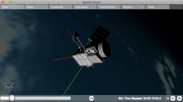
Defining a Pointing Line
Vizard can create a heading line from one object to another. For
example, it might be handy to create a line from the spacecraft pointing
towards the sun direction, or from the spacecraft towards Earth to know
how the antennas should point. These pointing lines can be scripted from
Basilisk as well using using a helper function createPointLine():
viz = vizSupport.enableUnityVisualization(scSim, simTaskName, scObject, saveFile=fileName)
vizSupport.createPointLine(viz, toBodyName='earth_planet_data', lineColor=[0, 0, 255, 255])
vizSupport.createPointLine(viz, toBodyName=“sun_planet_data”, lineColor=“yellow”)]
The createPointLine support macro requires the parameters toBodyName and lineColor to be
defined. The parameter fromBodyName is optional. If it is not
specified, then the viz.spacecraftName is used as a default origin.
The lineColor state can be either a string containing the color
name, or a list containing RGBA values. The support macro converts this
into the required set of numerical values.
Each pointing line message contains the three variables listed in the next table.
Variable |
Type |
Required |
Description |
|---|---|---|---|
|
string |
No, sc name default |
contains the name of the originating body |
|
string |
Yes |
contains the name of the body to point towards |
|
int(4) |
Yes |
color name or array on integer values specifying the RGBA values between 0 to 255 |
Defining Keep In/Out Cones
Vizard can create cones relative to the spacecraft which illustrated if
a body axis is within some angle to the sun (i.e. keep in cone), or if a
sensor axis is outside some angle to the sun (i.e. keep out cone). These
cones can be setup in Vizard, but can also be scripted from Basilisk
using the helper function createConeInOut:
viz = vizSupport.enableUnityVisualization(scSim, simTaskName, scObject, saveFile=fileName)
vizSupport.createConeInOut(viz, toBodyName='earth', coneColor='teal',
                       normalVector_B=[1, 0, 0], incidenceAngle=30\ macros.D2R, isKeepIn=True,
                       coneHeight=5.0, coneName=‘sensorCone’)
vizSupport.createConeInOut(viz,toBodyName='earth', coneColor='blue', normalVector_B=[0, 1, 0],
                       incidenceAngle=30\ macros.D2R, isKeepIn=False, coneHeight=5.0, coneName=‘comCone’)]
The following table illustrates the
arguments for the createConeInOut method:
Variable |
Type |
Units |
Required |
Description |
|---|---|---|---|---|
|
bool |
Yes |
make cone keep in (True) or keep out (False) |
|
|
string |
No, sc name default |
contains the name of the originating body |
|
|
string |
Yes |
contains the name of the body to point towards |
|
|
int(4) |
Yes |
color name or array on integer values specifying the RGBA values between 0 to 255 |
|
|
float(3) |
m |
No, (0,0,0) default |
position of the cone vertex |
|
float(3) |
m |
Yes |
normal axis of the cone in body frame components |
|
float |
rad |
Yes |
angle of the cone |
|
float |
rad |
Yes |
height of the cone |
|
string |
No |
cone label name, if unspecified viz will autogenerate name |
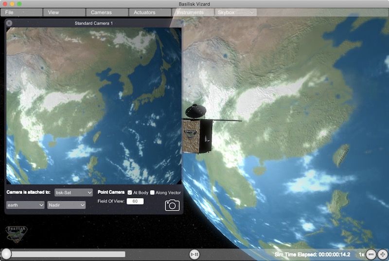
Defining the Vizard Camera View Panels
Vizard can create a spacecraft relative camera panel. This functionality can be
controlled by using the createStandardCamera helper method. The camera can
point in a body-fixed direction (setMode=1), or be aimed at a celestial target
(setMode=0). Multiple camera panels can be setup at the same time, and
they can be attached to different spacecraft through the spacecraftName argument.
viz = vizSupport.enableUnityVisualization(scSim, simTaskName, scObject, saveFile=fileName)
vizSupport.createStandardCamera(viz, setMode=0, bodyTarget='earth', setView=0)
vizSupport.createStandardCamera(viz, setMode=1, fieldOfView=60.*macros.D2R, pointingVector_B=[0.0, -1.0, 0.0])
The following table illustrates
the arguments for the createStandardCamera method.
Variable |
Type |
Units |
Required |
Description |
|---|---|---|---|---|
|
string |
No, sc name default |
name of the spacecraft with respect to which the camera is shown |
|
|
int |
No, default is 1 |
0 -> body targeting, 1 -> pointing vector |
|
|
int |
No, default is 0 |
0 -> Nadir, 1 -> Orbit Normal, 2 -> Along Track (default to nadir). This is a setting for body targeting mode. |
|
|
string |
No, default to first celestial body in messages |
Name of body camera should point to. This is a setting for body targeting mode. |
|
|
float |
rad |
No, default is -1 |
camera edge-to-edge field of view in the camera vertical |
|
float(3) |
No, default is (0,0,0) for auto placement |
Name of body camera should point to. This is a setting for pointing vector mode |
|
|
float(3) |
m |
No, default is (0,0,0) for auto placement |
If populated, ets camera position relative to parent body coordinate frame in meters using B frame components. If unpopulated camera is positioned automatically along camera view direction outside of parent body’s mesh to prevent obstruction of view. |
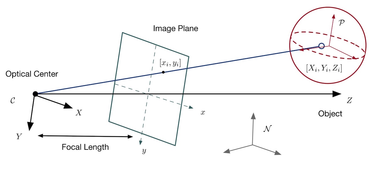
It is also possible to create a custom instrument camera view for opNav mode which points in an arbitrary direction as illustrate in the image above. The following helper method is an example of how such an instrument camera view can be created:
vizSupport.createCameraConfigMsg(viz, cameraID=1, fieldOfView=10 * macros.D2R,
                                     resolution=[1024, 1024], renderRate=0.1,
                                     cameraPos_B=[0.2, 0.1, 0.3], sigma_CB=[-1./3., 1./3., -1./3.])
Note that with this instrument camera Vizard will save off images the the user home folder at the rate
specified in renderRate. To avoid saving off images just make renderRate zero.
The camera frame is illustrated in the following image. It uses classical image image coordinates where x points
to the right, y point downwards and z points outward. More information is availabe in section 2.4.1 of
Dr. Teil’s dissertation.
The following tale illustrates the arguments for the
createCameraConfigMsg method.
Variable |
Type |
Units |
Required |
Description |
|---|---|---|---|---|
|
int |
Yes |
ID of the Vizard camera |
|
|
string |
No, sc name default |
name of the spacecraft with respect to which the camera is shown |
|
|
float |
rad |
yes |
edge-to-edge field of view in the camera vertical |
|
int(2) |
yes |
image sensor pixels |
|
|
float |
yes |
time between image grabs. 0 turns this off (default). |
|
|
float(3) |
m |
yes |
camera location relative to body frame in B frame components |
|
float(3) |
yes |
camera orientation relative to the body frame in MRPs |
|
|
string |
No |
Used to determine what star background should be shown. The empty string “” provides default NASA SVS Starmap, “ESO” shows the ESO Milky Way skybox, “black” provides a black background, or the user can provide a filepath to custom background image file. |
Defining the Custom Spacecraft Shape model
You can specify a custom OBJ model to be used with Vizard spacecraft representation. An sample is shown in the following screen capture.
This functionality can be controlled by using the ‘createCustomModel’ helper method.
viz = vizSupport.enableUnityVisualization(scSim, simTaskName, scObject, saveFile=fileName)
vizSupport.createCustomModel(viz,
                            modelPath="/Users/hp/Downloads/Topex-Posidon/Topex-Posidon-composite.obj",
                            scale=[2, 2, 10])
The following table illustrates the arguments for the createCustomModel method.
Variable |
Type |
Units |
Required |
Description |
|---|---|---|---|---|
|
string |
Yes |
Path to model obj -OR- “CUBE”, “CYLINDER”, or “SPHERE” to use a primitive shape |
|
|
string |
No, default is bsk-Sat |
Which bodies in scene to replace with this model, use “ALL_SPACECRAFT” to apply custom model to all spacecraft in simulation |
|
|
float(3) |
m |
No, default is (0,0,0) |
offset to use to draw the model |
|
float(3) |
rad |
No, default is (0,0,0) |
3-2-1 Euler angles to rotate CAD about z, y, x axes |
|
float(3) |
No, default is (1,1,1) |
desired model scale in x, y, z in spacecraft CS |
|
|
String |
No |
Path to texture to apply to model (note that a custom model’s .mtl will be automatically imported with its textures during custom model import). The image file types supported are: jpg, bmp, exr, gif, hdr, iff, pict, png, psd, tga, and tiff. The maximum image dimensions supported for runtime import are 16384 pixels by 16384 pixels. The image does not have to be square. |
|
|
string |
No |
Path to the normal map for the customTexture |
|
|
int |
No, default is -1 |
Value of -1 to use viz default, 0 for Unity Specular Standard Shader, 1 for Unity Standard Shader |
Specifying the Spacecraft Sprite Representation
In the spacecraft centric view a 3D model is rendered of the spacecraft. However, in planet and heliocentric views
the spacecraft is automatically represented as a 2D sprite (circle, triangle, etc.) if more than one
spacecraft is being simulated. The default sprite shape for all spacecraft can be set through the
defaultSpacecraftSprite value discussed above. To specify a specific sprite shape, and optional color, for a
specific spacecraft this can be done by setting the string variable spacecraftSprite inside the
spacecraft data structure.
The example scenario scenarioFormationBasic illustrates how to simulate multiple spacecraft. To make a spacecraft use a specific sprite representation use:
scData.spacecraftSprite = vizSupport.setSprite("STAR")
Specifying the Simulation Epoch Date and Time Information
Vizard can show the both the simulation time that has elapsed, or the mission time. If now epoch message has been set then Basilisk assumes a default January 1, 2019, 00:00:00 epoch time and date. The simulation time elapsed is thus the time since epoch. To specify a different simulation epoch data and time the EpochMsgPayload can be setup as discussed in scenarioMagneticFieldWMM. To tell Module: vizInterface what epoch message to read use:
viz.epochInMsg.subscribe(epochMsg)
An example of the use of this epoch message is shown in scenarioMagneticFieldWMM.
Specifying Reaction Wheel (RW) Information
The simplest method to include the RW states of a one more spacecraft in the Vizard data file is to
call vizSupport.enableUnityVisualization() with the additional argument:
rwEffectorList=rwStateEffector
Here rwStateEffector is an instance of a single Module: reactionWheelStateEffector which already has all
the spacecraft’s RW devices added to it. If you have multiple spacecraft, then use a list of RW effectors,
one effector per spacecraft:
rwEffectorList=[rwStateEffector1, rwStateEffector2]
This method is illustrated in the scenarioAttitudeFeedbackRW script. Note that this list must contain
one entry per spacecraft. If a spacecraft has no RW devices, then add None instead of an effector instance.
If custom RW state output messages are used, then the scData.rwInMsgs can be specified directly. This case
is employed in the test script test_dataFileToViz.
Specifying Thruster Information
The simplest method to include the clusters of thrusters of a one more spacecraft in the Vizard data file is to
call vizSupport.enableUnityVisualization() with the additional argument:
thrEffectorList=thrusterSet
Here thrusterSet is an instance of a single Module: thrusterDynamicEffector which already has all
the spacecraft’s THR devices added to this one THR cluster. If you have multiple spacecraft, or a spacecraft
has multiple clusters of THR devices such as ACS and DV thrusters, then use a double list of THR effectors.
The outer list has one entry per spacecraft, and the inner list has one entry per spacecraft THR cluster:
thrEffectorList=[[thrusterSet1Sc1, thrusterSet2Sc1], [thrusterSet1Sc2]]
The outer list must have one THR cluster list per spacecraft. If a spacecraft has no THR devices, then
add None instead of this cluster list.
The illustration of thrusters is shown in the example script scenarioAttitudeFeedback2T_TH.
Note that if the maximum force of a thruster is less than 0.01N (i.e. a micro-thruster), then the plume length is held the same as with a 0.01N thruster. Otherwise the micro-thruster plumes would not be visible.
If you want to change the thruster plume illustration color, then you can use the optional argument:
thrColors=vizSupport.toRGBA255("red")
This example is for a single spacecraft. If you have multiple spacecraft this must again be wrapped in a list
of lists as above. The inner list is the color you want to for each cluster. Thus, its dimension must match the
thrEffectorList double list dimension. If you want to keep the default color for a spacecraft then
add None as the cluster color.
The thruster information for each spacecraft can also be set directly by specifying sc.thrInMsgs and
sc.thrInfo directly as demonstrated in test_dataFileToViz.
Adding Location or Communication Stations
The Module: groundLocation is able to simulate a location on a celestial body like Earth.
The location can also be fixed to a satellite. Vizard will show a line between a satellite
and this location including if the satellite is within the
field of view of this location. Vizard can illustrate this ground location using the
addLocation() method, such as:
vizSupport.addLocation(viz, stationName="Boulder Station"
                       , parentBodyName='earth'
                       , r_GP_P=groundStation.r_LP_P_Init
                       , fieldOfView=np.radians(160.)
                       , color='pink'
                       , range=1000.0
                       )
The following table lists all required and optional arguments that can be provided to addLocation:
Variable |
Type |
Units |
Required |
Description |
|---|---|---|---|---|
|
string |
Yes |
Label of the ground location |
|
|
string |
Yes |
name of the planet object |
|
|
float(3) |
m |
Yes |
position vector of the location G relatiave to parent body (planet or spacecraft) frame P in P frame components |
|
float(3) |
No |
normal vector of the location station boresight, default is unit vector of |
|
|
float |
rad |
No |
edge-to-edge location station field of view, default is \(\pi\) |
|
int(4) |
No |
specify the location station color using RGBA value of 0-255 |
|
|
double |
m |
No |
range of the location station, use 0 or negative value (protobuffer default) to use viz default |
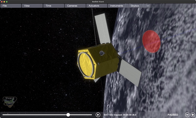
Adding Generic Sensor Visualization
Vizard can illustrate generic sensors in the 3d environments which have either a conical or rectangular field of view. For example, these sensors could be a camera, a star tracker or a fine sun sensor. Instead of making a specific visualization of such sensors, the generic sensor message allows a series of messages to be tied to a spacecraft and be configured to look like either sensor type. Further, an optional DeviceCmdMsgPayload message can be provided for each sensor such that the sensor state (active, inactive, etc.) can be visualized as well.
First, let’s discuss how to setup a generic sensor. The associated sensor structure and the required parameters are set using:
genericSensor = vizInterface.GenericSensor()
genericSensor.r_SB_B = [1., 1.0, 1.0]
genericSensor.fieldOfView = [20.0 * macros.D2R, -1]
genericSensor.normalVector = [0., 0., 1.]
The sensor location relative to the spacecraft B frame is given by r_SB_B. The sensor view axis is
set through normalVector. The fieldOfView is a vector with up to 2 floats. If a single positive value is provided,
then the sensor shape is a cone with this edge-to-edge field of view. If 2 positive floats are provided
then the sensor shape is a rectangle.
The full list of required and optional generic sensor parameters are provided in the following table.
Variable |
Type |
Units |
Required |
Description |
|---|---|---|---|---|
|
double[3] |
m |
Yes |
sensor location relative to body frame in body frame components |
|
double[3] |
Yes |
sensor view axis |
|
|
vector<float> |
rad |
Yes |
edge-to-edge field of view of cone (single positive float) or rectangle (two positive floats) |
|
bool |
No |
argument to hide the sensor visualization. Default value is |
|
|
double |
m |
No |
Value of 0 (protobuffer default) to show HUD at viz default size |
|
string |
No |
string to display on sensor label |
|
|
vector<int> |
No |
Send desired RGBA as values between 0 and 255, multiple colors can be populated in this field and will be assigned to the additional mode (Modes 0 and 1 will use the 0th color, Mode 2 will use the color indexed to 1, etc. If the mode number exceeds the number of colors provided then the default color is used again. |
|
|
int |
No |
set the sensor command state from python. Note that this value is replaced with the value from the sensor cmd input message if such an input message is provided. |
|
|
ReadFunctor<DeviceCmdMsgPayload> |
No |
sensor cmd input message |
Thus, to setup a sensor that uses red to display the location, orientation and status, you could use:
genericSensor = vizInterface.GenericSensor()
genericSensor.r_SB_B = [1., 1.0, 1.0]
genericSensor.fieldOfView.push_back(20.0 * macros.D2R)
genericSensor.fieldOfView.push_back(25.0 * macros.D2R)
genericSensor.normalVector = [0., 0., 1.]
genericSensor.color = vizInterface.IntVector(vizSupport.toRGBA255("red"))
genericSensor.label = "genSen1"
Note that here a rectangular 20x25 degree field of view is specified. To add a conical 20 degree field of view, then a single angle should be provided.
Next, each sensor can be connected to the optional device status message of type DeviceCmdMsgPayload:
cmdInMsg = messaging.DeviceCmdMsgReader()
cmdInMsg.subscribeTo(simpleInsControlConfig.deviceCmdOutMsg)
genericSensor.genericSensorCmdInMsg = cmdInMsg
The sensor command state can also be set directly from python using:
genericSensor.genericSensorCmd = 1
However, if the input message is specified then this value is replaced with the content of the input message.
Multiple generic sensors can be created for each spacecraft, and multiple spacecraft are supported. Using
the vizSupport.py file, the sensors are sent to Module: vizInterface using they keyword genericSensorList:
viz = vizSupport.enableUnityVisualization(scSim, simTaskName, scObject
                                          , saveFile=fileName
                                          , genericSensorList=genericSensor
                                          )
Note that here a single sensor and spacecraft is setup. If you have multiple sensors, or multiple spacecraft, then lists of lists are required:
viz = vizSupport.enableUnityVisualization(scSim, simTaskName, [scObject, scObject2]
                                          , saveFile=fileName
                                          , genericSensorList=[ [genericSensor1], [genericSensor2, genericSensor3] ]
                                          )
If the sensor has multiple activity types, such as taking a red, green, and blue color image, the DeviceCmdMsgPayload
message can have several positive command states. These distinct activity states can be visualized using multiple colors.
For example, to use red for state 1, green for state 2, you could use:
genericSensor.color = vizInterface.IntVector(vizSupport.toRGBA255("red") + vizSupport.toRGBA255("green"))
See scenarioGroundLocationImaging for an example of using the generic sensor visualization.
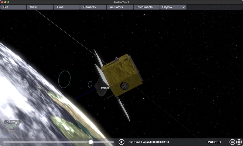
Adding Transceiver Visualization
Vizard can illustrate the state of an antenna in the 3d environments. The state can be either off (default), transmitting, receiving, or transmitting and receiving. The antenna communication state is dynamically set through an optional DataNodeUsageMsgPayload message. Note that this message contains a baud rate variable which dictactes if the module is transmitting data (negative baud rate) or receiving data (positive baud rate). Thus, a single transceiver HUD element can connect to a vector of DataNodeUsageMsgPayload input messages. These messages are scaned if they are transmitting, receiving or doing mix, and the transceiver state is set accordingly.
First, let’s discuss how to setup a transceiver HUD element. The associated structure and the required parameters are set using:
transceiverHUD = vizInterface.Transceiver()
transceiverHUD.r_SB_B = [0., 0., 1.]
transceiverHUD.fieldOfView = 40.0 * macros.D2R
transceiverHUD.normalVector = [0., 0., 1.]
The transceiver location relative to the spacecraft B frame is given by r_SB_B. The transceiver
bore sight axis is
set through normalVector. The fieldOfView sets the edge-to-edge field of view of this antenna communication
process.
The full list of required and optional transceiver parameters are provided in the following table.
Variable |
Type |
Units |
Required |
Description |
|---|---|---|---|---|
|
double[3] |
m |
Yes |
transceiver location relative to body frame in body frame components |
|
double[3] |
Yes |
transceiver center axis |
|
|
float |
rad |
Yes |
edge-to-edge field of the antenna communication access cone |
|
bool |
No |
argument to hide the transceiver visualization. Default value is |
|
|
int |
No |
Set transmission animation speed to a value between 1(slowest) to 10 (fastest), or 0 to use viz default |
|
|
string |
No |
string to display on transceiver label |
|
|
vector<int> |
No |
Send desired RGBA as values between 0 and 255. |
|
|
int |
No |
set the transceiver state from python. This can be 0 (off), 1 (sending), 2 (receiving) and 3 (sending and receiving). Note that this value is replaced with the value from the transceiver state input message if such an input message is provided. |
|
|
vector<ReadFunctor<DataNodeUsageMsgPayload>> |
No |
vector of transceiver communication state message(s) |
Thus, to setup a sensor that uses yellow to display the location, orientation and status, you could use:
transceiverHUD = vizInterface.Transceiver()
transceiverHUD.r_SB_B = [0., 0., 1.]
transceiverHUD.fieldOfView = 40.0 * macros.D2R
transceiverHUD.normalVector = [0., 0., 1.]
transceiverHUD.color = vizInterface.IntVector(vizSupport.toRGBA255("yellow", alpha=0.5))
transceiverHUD.label = "antenna"
Next, each sensor can be connected to the optional device status message of type DataNodeUsageMsgPayload:
trInMsg = messaging.DataNodeUsageMsgReader()
trInMsg.subscribeTo(transmitter.nodeDataOutMsg)
transceiverHUD.transceiverStateInMsgs.push_back(trInMsg)
The transceiver state can also be set directly from python using:
transceiverHUD.transceiverState = 1
However, if the input message is specified then this value is replaced with the content of the input message.
Multiple transceiver HUD elements can be setup for each spacecraft, and multiple spacecraft are supported. Using
the vizSupport.py file, the sensors are sent to Module: vizInterface using they keyword genericSensorList:
viz = vizSupport.enableUnityVisualization(scSim, simTaskName, scObject
                                          , saveFile=fileName
                                          , transceiverList=transceiverHUD
                                          )
Note that here a single transceiver and spacecraft is setup. If you have multiple sensors, or multiple spacecraft, then lists of lists are required:
viz = vizSupport.enableUnityVisualization(scSim, simTaskName, [scObject, scObject2]
                                          , saveFile=fileName
                                          , genericSensorList=[ None, [genericSensor2, genericSensor3] ]
                                          )
Here the first spacecraft has no transceiver, and the 2nd spacecraft has 2 transceivers.
See scenarioGroundLocationImaging for an example of using the generic sensor visualization.
Adding Storage Device Panel
Vizard can illustrate the state of storage devices (battery, data storage, fuel tank) in a 2D panel. A panel is create for each spacecraft, and the storage devices types are ordered with the panel. Each storage device state is illustrated on a horizontal bar chart. Hovering over the bar yields a popup with the current number. Thus, it is possible to have a spacecraft with multiple data storage devices, a large and small battery, as well as a single tank.
First, let’s discuss how to setup a generic storage element. The associated structure and the required parameters are set using:
hdDevicePanel = vizInterface.GenericStorage()
hdDevicePanel.label = "Main Disk"
The full list of required and optional generic storage parameters are provided in the following table.
Variable |
Type |
Units |
Required |
Description |
|---|---|---|---|---|
|
string |
Yes |
Name of storage device |
|
|
float |
variable |
No |
Current value of the storage device. If this is not set, then a storage status message must be connected to set this value. |
|
float |
No |
maximum absolute value of the storage device. If this is not set, then a storage status message must be connected to set this value. |
|
|
string |
No |
Units of stored quantity, i.e. “bytes”, “TB”, “kg”, etc. |
|
|
vector<int> |
No |
Send desired RGBA as values between 0 and 255, multiple colors can be populated in this field and will be used to color the bar graph between thresholds (i.e. the first color will be used between values of 0 and threshold 1, the second color will be used between threshold 1 and 2,…, the last color will be used between threshold n and the maxValue |
|
|
vector<int> |
No |
set the transceiver state from python. This can be 0 (off), 1 (sending), 2 (receiving) and 3 (sending and receiving). Note that this value is replaced with the value from the transceiver state input message if such an input message is provided. |
|
|
vector<ReadFunctor<PowerStorageStatusMsgPayload>> |
No |
incoming battery state msg, only connect one input message |
|
|
vector<ReadFunctor<DataStorageStatusMsgPayload>> |
No |
incoming data storage state msg, only connect one input message |
|
|
vector<ReadFunctor<FuelTankMsgPayload>> |
No |
incoming fuel tank state msg, only connect one input message |
Thus, to setup a data storage device that uses blue if the storage state is less than 80%, and orange if the storage is more than 80% full, you could use:
hdDevicePanel = vizInterface.GenericStorage()
hdDevicePanel.label = "Main Disk"
hdDevicePanel.units = "bytes"
hdDevicePanel.color = vizInterface.IntVector(vizSupport.toRGBA255("blue") + vizSupport.toRGBA255("orange"))
hdDevicePanel.thresholds = vizInterface.IntVector([80])
hdInMsg = messaging.DataStorageStatusMsgReader()
hdInMsg.subscribeTo(dataMonitor.storageUnitDataOutMsg)
hdDevicePanel.dataStorageStateInMsg = hdInMsg
Multiple storage panel elements can be setup for each spacecraft, and multiple spacecraft are supported. Using
the vizSupport.py file, the generic storage structures list is sent to Module: vizInterface using they keyword genericStorageList:
viz = vizSupport.enableUnityVisualization(scSim, simTaskName, scObject
                                          , saveFile=fileName
                                          , genericStorageList=hdDevicePanel
                                          )
Note that here a single storage device and spacecraft is setup. If you have multiple storage devices, or multiple spacecraft, then lists of lists are required:
viz = vizSupport.enableUnityVisualization(scSim, simTaskName, [scObject, scObject2]
                                          , saveFile=fileName
                                          , genericStorageList=[ None, [hdDevicePanel2, hdDevicePanel3] ]
                                          )
Here the first spacecraft has no transceiver, and the 2nd spacecraft has 2 transceivers.
See scenarioGroundLocationImaging for an example of using a data storage visualization. The example scenario_BasicOrbitMultiSat illustrates how to show a battery or fuel tank storage device.