BSK Scripting Settings
Overview
The About Vizard Unity-based visualization can have its settings scripted from a Basilisk python simulation script. This allows the user to write a BSK simulation script and specify in the same script what Vizard options should be used. Within Vizard the user can change these gain if needed. The BSK scripted Vizard settings are only used once at the beginning of the playback.
When calling the enableUnityVisualization macro method a copy of the
vizInterface module is returned. All scriptable Vizard settings are
stored inside the settings variable. For example, to set the Vizard
ambient lighting the following code is used:
viz = vizSupport.enableUnityVisualization(scSim, simTaskName, simProcessName, gravBodies=gravFactory, saveFile=fileName)
viz.settings.ambient = 0.5
If a setting is not provided, then the Vizard defaults are used. This allows the user to specify just a few or a lot of settings, as is appropriate.
Listing of all BSK Scriptable Vizard Settings
The following list contains the optional Vizard settings that can be specified. Only the settings used will be applied to Vizard. If a variable below is not specified, then it is not applied to Vizard and the Vizard default values are used.
General Settings
The following settings can be set directly using:
viz.settings.variableName = value
Note that for setting flags 1 means turn on, -1 means turn off, and a setting of 0 tells Vizard to use its own default setting for that behavior.
Variable |
Type |
Description |
|---|---|---|
|
[0,8] |
float value to specify the ambient Vizard lighting. |
|
(-1,1) |
flag to show (1) or hide (-1) the orbit trajectory lines |
|
(-1,1) |
flag to show (1) or hide (-1) the spacecraft coordinate axes |
|
(-1,1) |
flag to show (1) or hide (-1) the planet coordinate axes |
|
String |
Used determine what star background should be shown. The empty string “” provides default NASA SVS Starmap, “ESO” shows the ESO Milky Way skybox, “black” provides a black background, or the user can provide a filepath to custom background image file. |
|
(-1,1) |
flag to show (1) or hide (-1) the camera boresight line |
|
(-1,1) |
flag to show (1) or hide (-1) the camera cone |
|
(-1,1) |
flag to show (1) or hide (-) the coordinate system labels |
|
(-1,1) |
flag to show (1) or hide (-1) the celestial body labels |
|
(-1,1) |
flag to show (1) or hide (-1) the spacecraft labels |
|
(-1,1) |
flag to show (1) or hide (-1) the camera labels |
|
pos. integer |
GUI scaling factor, default is -1 which uses Vizard default. |
|
string |
Set sprite for ALL spacecraft through shape name and optional int RGB color values [0,255].
Possible settings: |
|
(-1,1) |
Flag to show spacecraft as sprites if their visual size gets too small |
|
(-1,1) |
Flag to show celestial bodies as sprites if their visual size gets too small |
|
(-1,1) |
Flag to make mission date/time use a 24h clock instead of a 12h clock with am/pm |
|
(-1,1) |
Flag to show the data frame rate |
Setting Actuator GUI Options
To specify the actuator GUI settings use the setActuatorGuiSetting
helper method in Python. An example is:
vizSupport.setActuatorGuiSetting(viz, viewRWPanel=True, viewRWHUD=True)
The following table includes the keyword options for this method.
viz.settings.variableName = value
Variable |
Type |
Required |
Description |
|---|---|---|---|
|
Boolean |
No |
Show the thruster panel |
|
Boolean |
No |
Show the thruster particle streams |
|
Boolean |
No |
Show the thruster labels |
|
Boolean |
No |
Show the reaction wheel panel |
|
Boolean |
No |
Show the reaction wheel disks configuration outside the spacecraft |
|
Boolean |
No |
Show the reaction wheel labels |
|
string |
No, sc name default |
Specify which spacecraft should show actuator information. If not provided then
the |
Defining a Pointing Line
Vizard can create a heading line from one object to another. For
example, it might be handy to create a line from the spacecraft pointing
towards the sun direction, or from the spacecraft towards Earth to know
how the antennas should point. These pointing lines can be scripted from
Basilisk as well using using a helper function createPointLine():
viz = vizSupport.enableUnityVisualization(scSim, simTaskName, simProcessName, gravBodies=gravFactory, saveFile=fileName)
vizSupport.createPointLine(viz, toBodyName='earth', lineColor=[0, 0, 255, 255]) vizSupport.createPointLine(viz, toBodyName=“sun”, lineColor=“yellow”)]
The createPointLine support macro requires the parameters toBodyName and lineColor to be
defined. The parameter fromBodyName is optional. If it is not
specified, then the viz.spacecraftName is used as a default origin.
The lineColor state can be either a string containing the color
name, or a list containing RGBA values. The support macro converts this
into the required set of numerical values.
Each pointing line message contains the three variables listed in the next table.
Variable |
Type |
Required |
Description |
|---|---|---|---|
|
string |
No, sc name default |
contains the name of the originating body |
|
string |
Yes |
contains the name of the body to point towards |
|
int(4) |
Yes |
color name or array on integer values specifying the RGBA values between 0 to 255 |
Defining Keep In/Out Cones
Vizard can create cones relative to the spacecraft which illustrated if
a body axis is within some angle to the sun (i.e. keep in cone), or if a
sensor axis is outside some angle to the sun (i.e. keep out cone). These
cones can be setup in Vizard, but can also be scripted from Basilisk
using the helper function createConeInOut:
viz = vizSupport.enableUnityVisualization(scSim, simTaskName, simProcessName, gravBodies=gravFactory, saveFile=fileName)
vizSupport.createConeInOut(viz, toBodyName='earth', coneColor='teal', normalVector_B=[1, 0, 0], incidenceAngle=30\ macros.D2R, isKeepIn=True, coneHeight=5.0, coneName=‘sensorCone’)
vizSupport.createConeInOut(viz,toBodyName='earth', coneColor='blue', normalVector_B=[0, 1, 0], incidenceAngle=30\ macros.D2R, isKeepIn=False, coneHeight=5.0, coneName=‘comCone’)]
The following table illustrates the
arguments for the createConeInOut method:
Variable |
Type |
Units |
Required |
Description |
|---|---|---|---|---|
|
bool |
Yes |
make cone keep in (True) or keep out (False) |
|
|
string |
No, sc name default |
contains the name of the originating body |
|
|
string |
Yes |
contains the name of the body to point towards |
|
|
int(4) |
Yes |
color name or array on integer values specifying the RGBA values between 0 to 255 |
|
|
float(3) |
m |
No, (0,0,0) default |
position of the cone vertex |
|
float(3) |
m |
Yes |
normal axis of the cone in body frame components |
|
float |
rad |
Yes |
angle of the cone |
|
float |
rad |
Yes |
height of the cone |
|
string |
No |
cone label name, if unspecified viz will autogenerate name |
Defining the Vizard Camera View Panels
Vizard can create a spacecraft relative camera panel. This functionality can be
controlled by using the createStandardCamera helper method. The camera can
point in a body-fixed direction (setMode=1), or be aimed at a celestial target
(setMode=0). Multiple camera panels can be setup at the same time, and
they can be attached to different spacecraft through the spacecraftName argument.
viz = vizSupport.enableUnityVisualization(scSim, simTaskName, simProcessName,
gravBodies=gravFactory, saveFile=fileName)
vizSupport.createStandardCamera(viz, setMode=0, bodyTarget='earth', setView=0)
vizSupport.createStandardCamera(viz, setMode=1, fieldOfView=60.*macros.D2R, pointingVector_B=[0.0, -1.0, 0.0])
The following table illustrates
the arguments for the createStandardCamera method.
Variable |
Type |
Units |
Required |
Description |
|---|---|---|---|---|
|
string |
No, sc name default |
name of the spacecraft with respect to which the camera is shown |
|
|
int |
No, default is 1 |
0 -> body targeting, 1 -> pointing vector |
|
|
int |
No, default is 0 |
0 -> Nadir, 1 -> Orbit Normal, 2 -> Along Track (default to nadir). This is a setting for body targeting mode. |
|
|
string |
No, default to first celestial body in messages |
Name of body camera should point to. This is a setting for body targeting mode. |
|
|
float |
rad |
No, default is -1 |
camera edge-to-edge field of view in the camera vertical |
|
float(3) |
No, default is (0,0,0) for auto placement |
Name of body camera should point to. This is a setting for pointing vector mode |
|
|
float(3) |
m |
No, default is (0,0,0) for auto placement |
If populated, ets camera position relative to parent body coordinate frame in meters using B frame components. If unpopulated camera is positioned automatically along camera view direction outside of parent body’s mesh to prevent obstruction of view. |
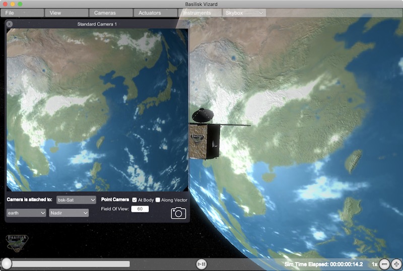
It is also possible to create a custom instrument camera view for opNav mode which points in an arbitrary direction as illustrate in the image above. The following helper method is an example of how such an instrument camera view can be created:
vizSupport.createCameraConfigMsg(viz, cameraID=1, fieldOfView=10 * macros.D2R,
                                     resolution=[1024, 1024], renderRate=0.1,
                                     cameraPos_B=[0.2, 0.1, 0.3], sigma_CB=[-1./3., 1./3., -1./3.])
Note that with this instrument camera Vizard will save off images the the user home folder at the rate
specified in renderRate. To avoid saving off images just make renderRate zero.
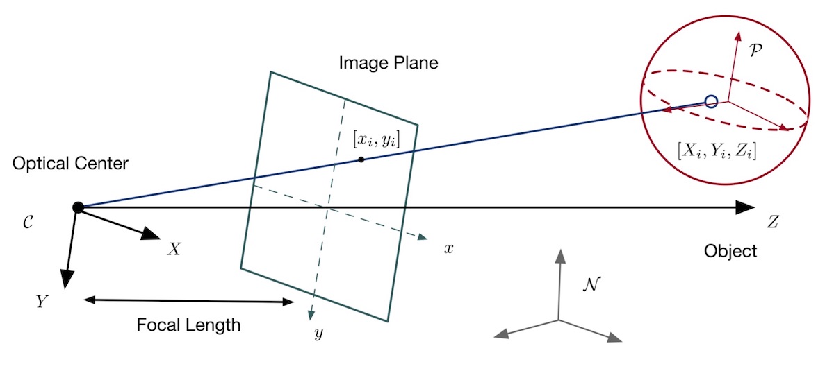
The camera frame is illustrated in the following image. It uses classical image image coordinates where x points
to the right, y point downwards and z points outward. More information is availabe in section 2.4.1 of
Dr. Teil’s dissertation.
The following tale illustrates the arguments for the
createCameraConfigMsg method.
Variable |
Type |
Units |
Required |
Description |
|---|---|---|---|---|
|
int |
Yes |
ID of the Vizard camera |
|
|
string |
No, sc name default |
name of the spacecraft with respect to which the camera is shown |
|
|
float |
rad |
yes |
edge-to-edge field of view in the camera vertical |
|
int(2) |
yes |
image sensor pixels |
|
|
float |
yes |
time between image grabs. 0 turns this off (default). |
|
|
float(3) |
m |
yes |
camera location relative to body frame in B frame components |
|
float(3) |
yes |
camera orientation relative to the body frame in MRPs |
|
|
string |
No |
Used to determine what star background should be shown. The empty string “” provides default NASA SVS Starmap, “ESO” shows the ESO Milky Way skybox, “black” provides a black background, or the user can provide a filepath to custom background image file. |
Defining the Custom Spacecraft Shape model
You can specify a custom OBJ model to be used with Vizard spacecraft representation. An sample is shown in the following screen capture.
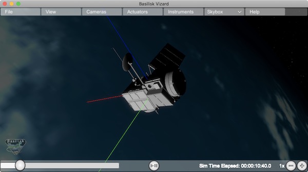
This functionality can be controlled by using the ‘createCustomModel’ helper method.
viz = vizSupport.enableUnityVisualization(scSim, simTaskName, simProcessName,
gravBodies=gravFactory, saveFile=fileName)
vizSupport.createCustomModel(viz,
                            modelPath="/Users/hp/Downloads/Topex-Posidon/Topex-Posidon-composite.obj",
                            scale=[2, 2, 10])
The following table illustrates the arguments for the createCustomModel method.
Variable |
Type |
Units |
Required |
Description |
|---|---|---|---|---|
|
string |
Yes |
Path to model obj -OR- “CUBE”, “CYLINDER”, or “SPHERE” to use a primitive shape |
|
|
string |
No, default is bsk-Sat |
Which bodies in scene to replace with this model, use “ALL_SPACECRAFT” to apply custom model to all spacecraft in simulation |
|
|
float(3) |
m |
No, default is (0,0,0) |
offset to use to draw the model |
|
float(3) |
rad |
No, default is (0,0,0) |
3-2-1 Euler angles to rotate CAD about z, y, x axes |
|
float(3) |
No, default is (1,1,1) |
desired model scale in x, y, z in spacecraft CS |
|
|
String |
No |
Path to texture to apply to model (note that a custom model’s .mtl will be automatically imported with its textures during custom model import) |
|
|
string |
No |
Path to the normal map for the customTexture |
|
|
int |
No, default is -1 |
Value of -1 to use viz default, 0 for Unity Specular Standard Shader, 1 for Unity Standard Shader |
Specifying the Spacecraft Sprite Representation
In the spacecraft centric view a 3D model is rendered of the spacecraft. However, in planet and heliocentric views
the spacecraft is automatically represented as a 2D sprite (circle, triangle, etc.) if more than one
spacecraft is being simulated. The default sprite shape for all spacecraft can be set through the
defaultSpacecraftSprite value discussed above. To specify a specific sprite shape, and optional color, for a
specific spacecraft this can be done by setting the string variable spacecraftSprite inside the
spacecraft data structure.
The example scenario scenarioFormationBasic illustrates how to simulate multiple spacecraft. To make a spacecraft use a specific sprite representation use:
scData.spacecraftSprite = vizSupport.setSprite("STAR")
Specifying the Simulation Epoch Date and Time Information
Vizard can show the both the simulation time that has elapsed, or the mission time. If now epoch message has been set then Basilisk assumes a default January 1, 2019, 00:00:00 epoch time and date. The simulation time elapsed is thus the time since epoch. To specify a different simulation epoch data and time the epochSimMsg can be setup as discussed in scenarioMagneticFieldWMM. To tell ref:vizInterface what epoch message to read use:
viz.epochMsgName = "Epoch_Msg_Name_Used"
An example of the use of this epoch message is shown in scenarioMagneticFieldWMM.