User Guide
Startup Panel
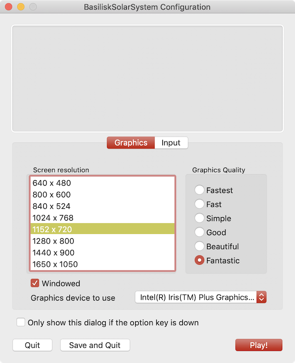
hen starting up the Vizard software the user is presented with a resolution and graphics setting option panel as shown above. There is an option on the lower portion of this panel to turn off this plane on start-up and only show it if the program is started while pressing the option key. Note that the Vizard screen size can be dynamically changed after startup as well.
Next Vizard presents a panel where the user can select which simulation to visualize. To play back a previously recorded BSK simulation press the Select button and navigate to the binary BSK recording file. After a file has been selected press the Start Visualization button.
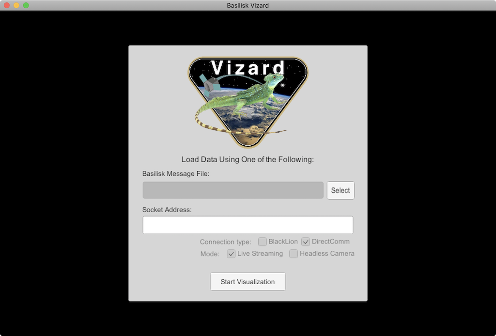
To live stream data from a running Basilisk simulation to Vizard make sure that the connection type is DirectComm and the mode is Live Streaming. When starting a Basilisk script that uses live streaming (see scenarioBasicOrbitStream) the socket address, such as tcp://localhost:5556, is shown in the terminal window. Copy this and paste it into the Vizard socket address text field. Finally press the Start Visualization button to begin the visualization.
View Modes
To engage with the visualization, the view point can be rotated and the user can zoom in and out. There are three view modes available:
Spacecraft-Centric View Mode (default): Here the spacecraft is drawn 1:1 while showing other celestial objects about it. When rotating the center of the spacecraft is the center of rotation. The spacecraft trajectory is not shown in this view. You can zoom in and out locally, but if you zoom out too far then the view mode switched to a planet-centric view mode.
Planet-Centric View Mode: Here a planet-wide view is presented. When rotating the view point this is about with the center of the planet as the center of rotation. The spacecraft trajectory is shown. The spacecraft is drawn at an exaggerated size so it is visible as a 3D object in this view. To return to a spacecraft-centric view mode double click on the spacecraft. If you zoom out far enough then the mode switches to a heliocentric view.
Heliocentric View Mode: Here a solar system wide view is shown. The planets are drawn enlarged to make them visible, and the planet trajectories are shown as well. If the spacecraft is orbiting a planet it is not visible in this view. If the spacecraft is on a heliocentric trajectory it is shown, also enlarged, in this view. Double clicking on a planet returns the user to a planet-centric view.
Space Vehicle States
The following sections describe the basic user interface elements of Vizard. Some settings can be set via a Basilisk script as discribed in the BSK Scripting Settings.
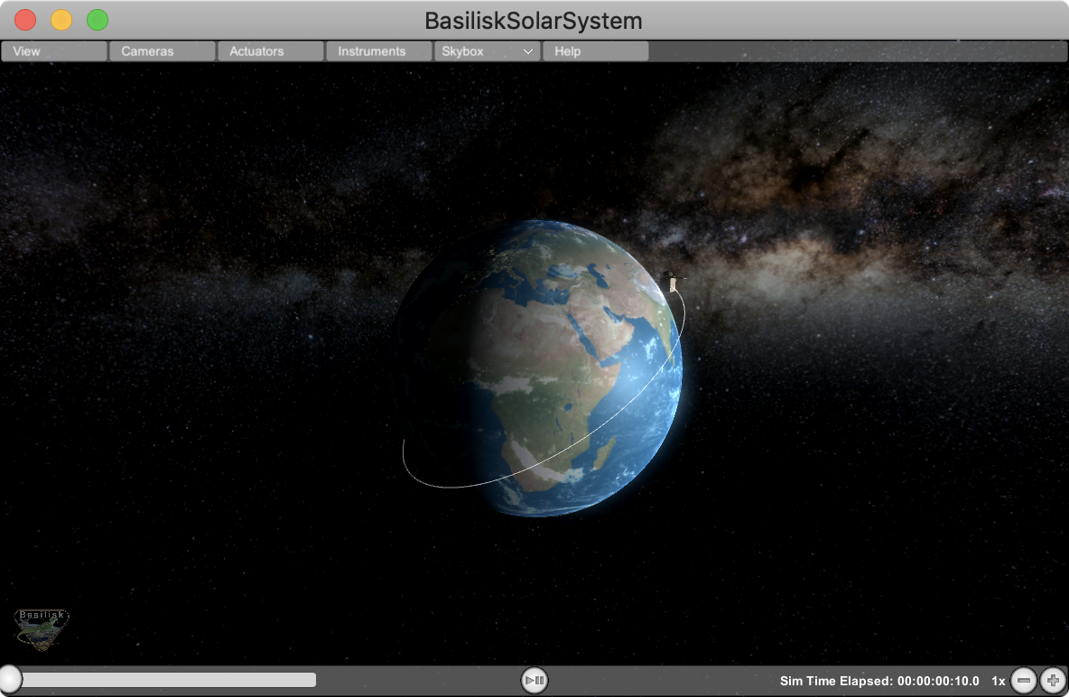
Basic Position and Orientation
Vizard is able to show the position and orientation of the spacecraft being simulated. If one or more planets are being modeled, then the spacecraft is show relative to the nearest planet.
Reaction Wheel States
If Reaction Wheels or RWs are modeled, then a RW panel can be opened
from within the Actuator menu bar item. Here the RW wheel speeds and
motor torques are shown.
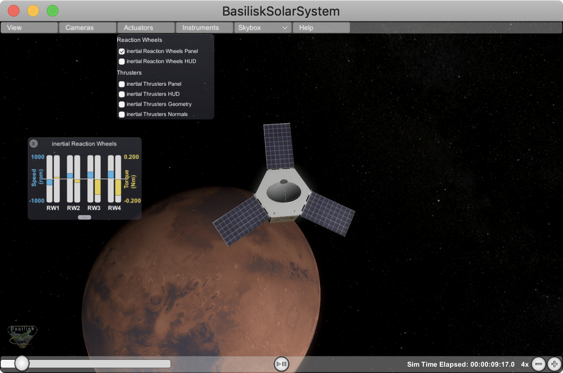
Thruster States
Actuator menu item. The options include to open
a Thruster Panel which shows the thruster firings as bar charts. The
thruster HUD uses a particle engine to illustrate if a thruster is
firing. Here the length and density of the particles is related to the
strength and duty cycle of the thruster. The thruster geometry option
draws small cones where the thrusters are modeled to be. This is
useful when debugging that a thruster configuration is being properly
modeled. Finally, the thruster normals option illustrates the thrust
axes being modeled.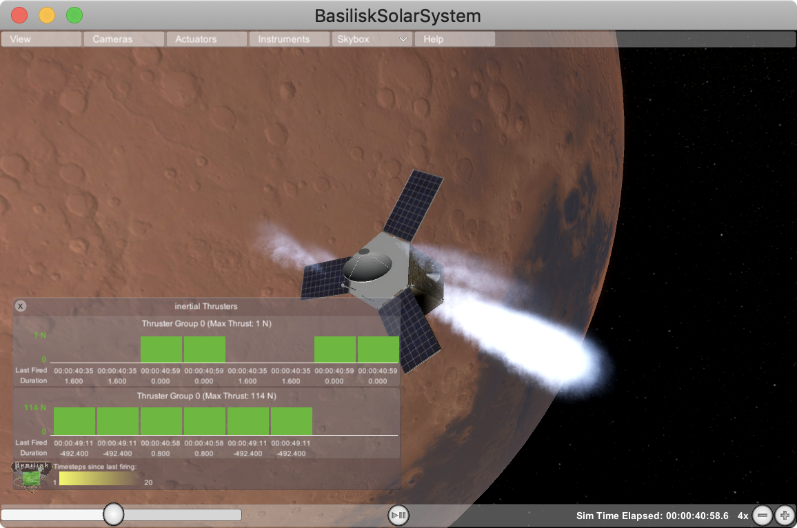
Vizard Configuration Options
View Menu Item
View menu tab contains a range of Vizard options. A range of
coordinate frames can be toggled on or off.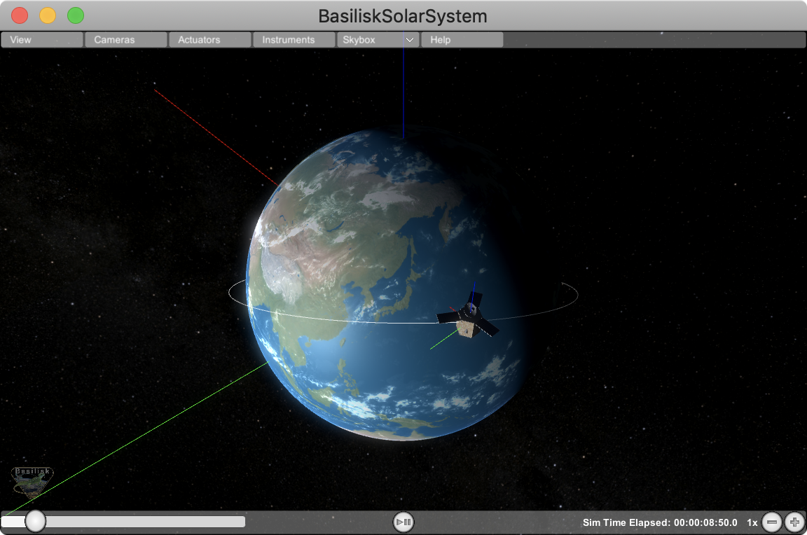
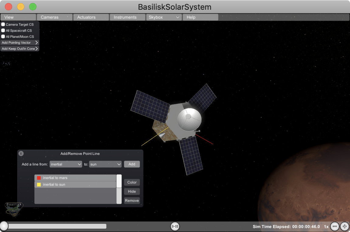
Add Pointing Vector
This allows a line to be drawn from the spacecraft aimed at another celestial body such as the sun, a planet, etc. The spacecraft location is referred to as “Inertial”. The purpose of these lines is to have a quick visual reference in what direction another body is located. The lines can be hidden or removed as needed. Some celestial bodies come with default colors such as yellow for sun heading, or red for Mars heading, etc. However, each line color can be customized as needed.
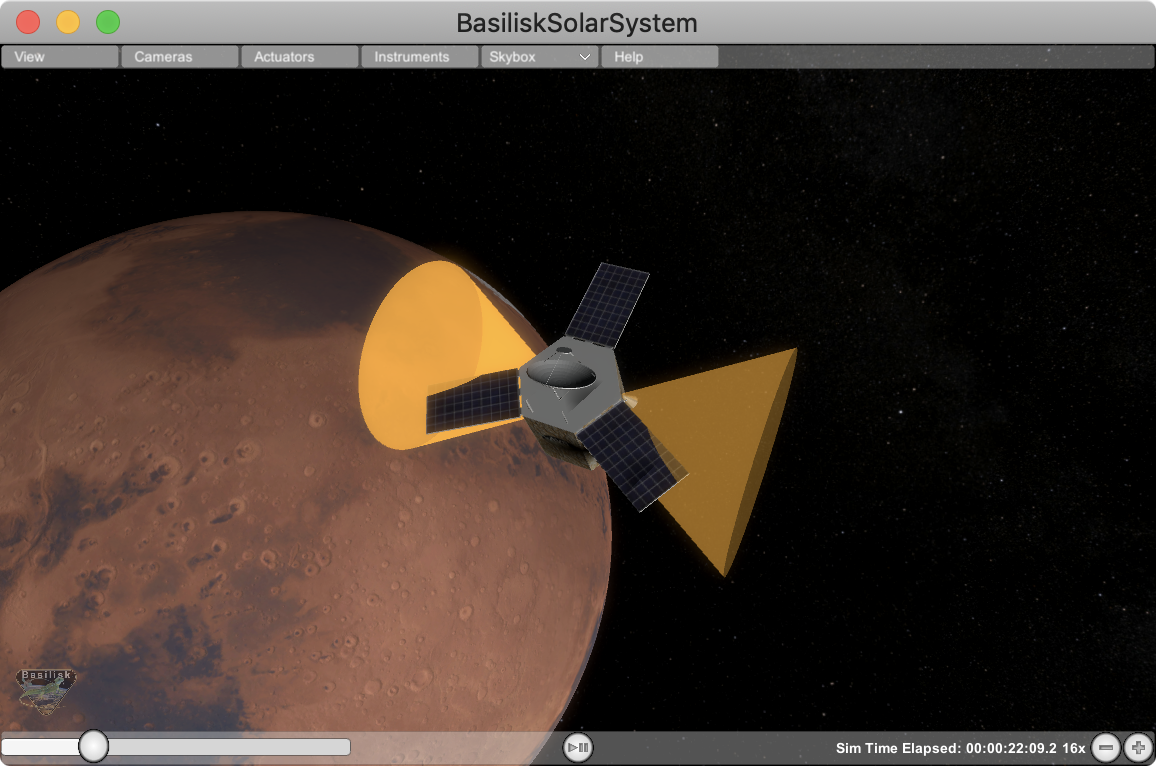
Add Keep Out/In Cone
This feature allows for a cone to be added relative to the spacecraft which indicates if a cone about a particular body-fixed axis intersects with a celestial object. For example, this can be used to add a cone to validate that the sensor axis doesn’t get too close to the sun (keep out cone), or if the solar panel normal axis stays within some cone to the sun (keep in cone). If the cone in/out condition is not triggered, then the cone is opaque. If the in/out condition is triggered, then the cone becomes solid.
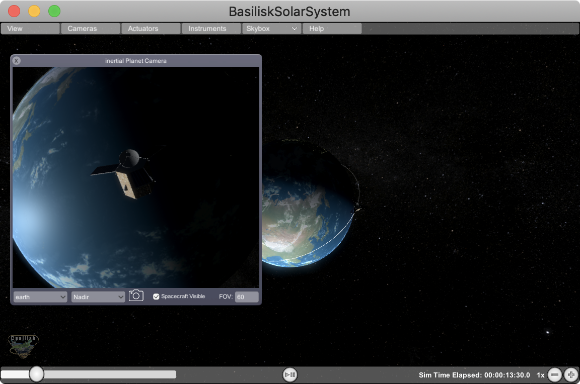
Inertial Planet Camera
This is a camera whose view always points relative to a particular celestial body. The user can set the field of view value, as well as grab a screen shot if needed. The user can select relative to which planet the camera should point, and if the camera should point along orbit axis, along track or orbit normal.
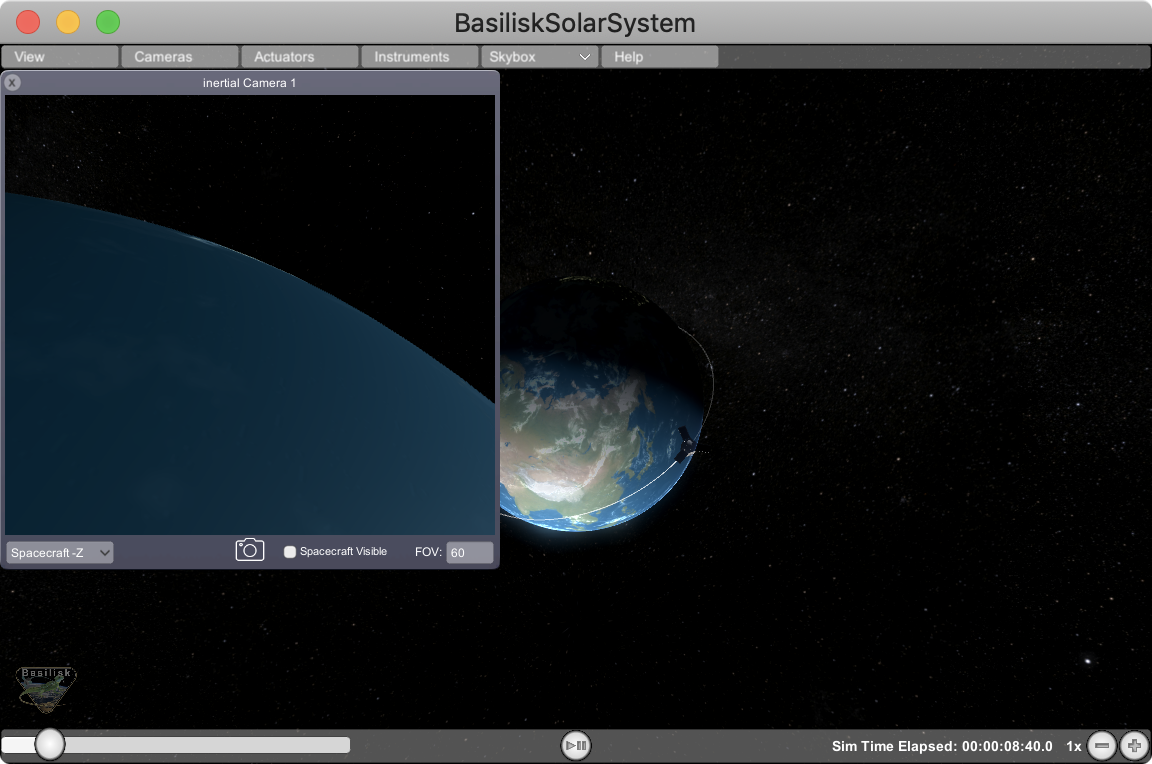
Inertial Camera
Up to two custom views can be generated that look out of the spacecraft +/- x-, y- and z-axis. Again the field of view can be configured, and a screen grab button is present.
Skybox Menu Item
The default star field is a realistic NASA star field. The alternate option is an ESO Milky Way star field that is more visually pleasing, but less realistic.